|
 |
|
Printable Version |
Site Map
|
Tracking, Safety, and Navigation System for Firefighters
|
This paper was presented by Wayne Haase at the 2003 Fire Department Instructors' Conference (FDIC) in Indianapolis, IN. It was
presented in conjunction with the
Institute of Fire Engineers and
John Jay College, during the "Command, Control, and
Communications: Assessing the New Technology" Conference. The paper was presented along with a Powerpoint presentation.
To view the PDF version of the paper or the Powerpoint presentation, click on the appropriate icon below:
| |
|

|
|
- Tracking, Safety, and Navigation System for Firefighters Paper (pdf) |
|
|
|
|
|
- Tracking, Safety, and Navigation System for Firefighters Presentation Notes (pdf) |
|
|
|

|
|
- Powerpoint Presentation (ppt) |
|
|
|
Tracking, Safety, and Navigation System for Firefighters
Wayne C. Haase, PhD
Malcolm MacGregor, CFEI
Zachary S. Haase
|
1.0 Introduction
Firefighting is a dangerous and difficult job performed in a hostile environment. During a fire the atmosphere inside a burning
structure can rapidly fill with dense smoke that can reduce visibility to only a few inches and render hand lights useless. The
temperature within the structure can range from 200°F to 400°F near the floor and often be between 1000°F to 2000°F
near the ceiling. Flashover can cause instantaneous incineration of virtually all combustible material. A firefighter who has become
separated, disoriented, or disabled in this setting needs to be located very quickly to prevent an injury from occurring or to be
rescued after an injury has occurred. If the location of the firefighter is not known, an area search must be performed. The
difficulty of performing an area search is compounded by the firefighters own equipment, which typically includes a helmet, Nomex
hood, air supply, coat, trousers, boots, and gloves that are designed to encapsulate and protect the firefighter from the surrounding
hostile environment. This equipment, which may weigh in the range of 50-70 lbs, makes movement difficult and restricts visibility,
hearing, and verbal communications.
Search techniques for locating disabled firefighters and/or civilians have not changed much since Ben Franklin headed the
Philadelphia Fire Brigade. Search teams, connected to the exit by safety ropes, crawl on hands and knees swinging axe handles or
haligan tools to try to locate the victim by feel. The technique is slow, cumbersome, and not very effective. Search times for
relatively small areas often require upwards of fifteen to thirty minutes, far too long for successful rescue. If the search team
had a device or system that indicated the precise direction of the path to the fallen firefighter, search and rescue times could be
dramatically reduced.
Two products have been added to the firefighters search and rescue arsenal in the last twenty years, the Personal Alert Safety
System (PASS) and the Thermal Imaging Camera (TIC). While these systems represent significant technological advances for the industry,
both have limitations when it comes to identifying the specific location and route to a fallen firefighter in an actual fire
environment. In December, 1999, six career firefighters perished in the Worcester Massachusetts Warehouse Fire. Their integrated
PASS devices were activated and a TIC was used. The rescuers ropes became entangled in the grid of columns in the building, the
PASS devices were impossible to locate in the limited time available, and the TIC experienced thermal overload. As a result, the
second and third pair of rescuers sent in to locate the first pair could locate neither the previous pairs nor the exit in the
maze-like structure. The relative advantages and disadvantages of these products will be further discussed later in this paper.
While many factors contributed to the Worcester tragedy, the limitations of existing locator technology loomed large. The founders
of Summit Safety, Inc., followed the unfolding story at first with sadness, and then with resolve to find a suitable technology that
could overcome these limitations. This paper discusses the possible technologies and describes a new system, the Personnel Ultrasonic
Locating Safety Equipment, or Pulse, which is capable of significantly reducing search times for locating firefighters and exits by
identifying the actual path to the target. The patented Pulse system is able to operate within the hostile environment of a burning
structure without being adversely affected by the smoke, heat, or the structure itself.
2.0 Comparison of Locating/Finding Techniques
Independent of the choice of technologies, there are other system considerations related to the design of a tracking and navigation
system. One important issue involves the difference between knowing the location of the fallen firefighter and actually following a
path to reach the firefighter. For example, the goal of a tracking and navigation system might be to simply tell the Incident
Commander that a firefighter is 50 feet forward and 30 feet to the right of the front door. On the other hand, the goal might be to
guide a rapid intervention team (RIT) so that they can navigate directly to the firefighter. A search operation might be content to
simply know the location of the target as seen on a computer display screen; a rescue operation requires that the searcher actually
navigate to the exact location of the target. The difference is perhaps best illustrated by a childs maze: from a birds-eye-view,
you can easily identify the start and finish of the maze, but the challenge is to find the path connecting the start to the finish.
Walls and blind alleys block many of the possible paths.
In order to identify the path to the firefighter, several techniques can be used, including a blind search, a homing beacon, an
active search, and triangulation. From a technical standpoint, the preferred way to determine the path is by means of a homing beacon,
as will be shown in the following discussion.
2.1 Blind Search
A blind search occurs whenever the search team has no information concerning the direction or distance to the disabled firefighter.
The example discussed above rescuers on hands and knees locating the firefighter by feel is a blind search. The rescuers could
be two feet away from the victim and not know it. In order to be successful, the searchers must visit all areas in the search
pattern. If they miss a part of the area, they might miss the victim. This method is slow and not always successful.
2.2 Homing Beacon
This method requires the disabled firefighter to wear a homing beacon that transmits a signal detectable by the searcher. The
method is quite similar to passive sonar: one submarine listens for the sounds of a second submarine. This is also the method used
by mariners to find a known landmark: they use their eyes to look for a lighthouse. Two items are required for this method: (1) an
omnidirectional transmitter carried by the disabled firefighter, and (2) a directional receiver carried by the search team. Since
the transmitter is omnidirectional, the power in the signal detected by the directional receiver will generally be inversely
proportional to the square of the distance between the transmitter and receiver. This method is typically much faster than the
blind search because the rescuer is always directed toward the disabled firefighter. Furthermore, if the searcher can measure the
signal strength from the beacon, he has an approximate measure of the distance to the firefighter.
2.3 Active Search
This method is similar to active sonar: one submarine transmits a sonar pulse and listens for reflections from a second submarine.
In this case, the only requirement on the disabled firefighter is that he be able to reflect or scatter the signal; he would not
have to carry a transmitter. Both the transmitter and the receiver would be in the hands of the search team. The power loss for a
system of this type would generally be inversely proportional to the fourth power of the distance between the search team and the
firefighter: the power in the signal that reaches the firefighter would be reduced by the square of the distance, and the reflected
signal would be further reduced by an additional factor of the square of the distance. Compared to the homing beacon system above,
the power losses would typically be significantly higher. Because of the much higher loss of signal power, this type of system would
generally have a much shorter distance capability than the homing beacon method.
Another problem with an active search system concerns multiple reflectors. If most of the environment is filled with reflectors,
distinguishing the desired target can be quite difficult. In the case of submarine sonar, active techniques work best in open water,
where the only echo is due to the other submarine. Consider the task of finding a person in a house of mirrors: multiple reflections
make finding the person very difficult. For a fire environment, this method would be quite difficult to implement.
2.4 Triangulation
The triangulation method involves determining the distance or direction of the target from known positions. The Global Positioning
System (GPS) is an example: a hand-held receiver measures the distance between the receiver and several orbiting satellites (whose
position is known quite accurately) and calculates the receivers location.
The triangulation method is more appropriate to determining the position of the victim, but not the path to the victim. In order
to determine the path to the victim, a map would be required. If no map is available, then the searcher would head in the general
direction of the victim, but would have to learn the location of the walls and obstacles in the process. One problem with not having
a detailed and accurate map is that a rescuer could work his way to the corner of a room and then discover that he was only two feet
away from the victim, but on the wrong side of a concrete wall. He would then have to do a blind search to follow the wall in order
to find the path to the victim.
3.0 Technology Choices for Fire Environment
A number of different technologies are available for the design of a tracking and navigation system, including optics,
electromagnetics and acoustics. This section discusses the relative merits of each of these technologies with regard to use in a
fire environment. All three technologies are associated with propagation of waves; optical and radio waves are electromagnetic
in nature, whereas acoustic waves are pressure waves. Electromagnetic waves will propagate in a vacuum, while acoustic waves require
a propagating medium, such as air, water, or metal.
Many of the wave properties, including the shape of the beam and the degree of interaction with smoke particles, are governed by
the wavelength of the traveling wave. Knowledge of the wavelength provides a way to compare the different technologies and their
suitability for a tracking and navigation system for use in the fire environment.
For any wave at frequency f, the wavelength, L, and propagating at velocity, c, are related by:
|
c = f * L
|
(3-1)
|
Typical numbers (arranged in order of increasing wavelength) are shown in Table 3-1.
|
Technology |
Wave Velocity |
Frequency |
Wavelength |
|
Visible Light |
3 x 10⁸ m/s |
4 x 10¹⁴ Hz |
0.75 um (0.000030 in = 30 u in) |
|
Infrared Light |
3 x 10⁸ m/s |
3 x 10¹⁴ Hz |
1 um (0.000039 in = 39 u in) |
|
Infrared Light |
3 x 10⁸ m/s |
2.1 x 10¹³ Hz |
14 um (0.000562 in = 562 u in) |
|
Ultrasound |
330 m/s |
40 KHz |
8.25 mm (0.325 in) |
|
Radio (microwave) |
3 x 10⁸ m/s |
2.4 GHz |
125 mm (4.9 in) |
|
Radio (GPS) |
3 x 10⁸ m/s |
1.575 GHz |
191 mm (7.5 in) |
|
Audible Sound |
330 m/s |
1 KHz |
330 mm (13 in) |
|
Radio (FM) |
3 x 10⁸ m/s |
100 MHz |
3 m (9.84 ft) |
|
Radio (AM) |
3 x 10⁸ m/s |
1 MHz |
300 m (984 ft) |
| |
|
Table 3-1. Wavelengths for Different Technologies |
3.1 Optical: Visible
The most obvious search technology is visible light: rescuers simply look (with their eyes) for the victim. If no light is present,
the rescuer uses a flashlight to illuminate the search direction. The method is restricted to line of sight; that is, one cannot
locate a victim behind an obstacle, such as a desk or sofa, without physically looking around the obstacle. Visible light is
reflected by mirrors, but not by most surfaces, such as walls. Visible light does not penetrate walls.
The actual temperature of the fire environment has only a very slight effect on visible light. A change in temperature causes a
change in dielectric constant of air, which in turn causes a slight change in index of refraction for visible light. As a result, an
image can become slightly blurred due to local differences in temperature. This rippling effect is often seen when looking over a
hot surface, such as a parking lot on a hot summers day.
Water particles, either as spray from a fire hose, or as condensed steam from the fire, can also cause scattering and reflections
or refractions of the visible light.
Visible light works well as long as no smoke is present. The mechanism by which smoke obscures visibility is called Rayleigh
scattering, and is due to the interaction by particles significantly smaller than the wavelength of the light on the propagating
light wave. In terms of the power in the wave, Rayleigh scattering is inversely proportional to fourth power of wavelength. Because
of this relationship, the sky is blue and sunsets are red. Rayleigh scattering also affects the other technologies discussed in this
paper; the degree to which the particular technology is affected is determined by the wavelength of that technology. Those
technologies higher in Table 3-1 have shorter wavelengths and are thus more affected by smoke than those lower in the table.
3.2 Optical: Infrared (Thermal)
Infrared technology is quite similar to visible light, the primary difference being that the wavelength is longer. The frequency
of the wave is below that of red light, hence infrared. The longer wavelength portion of the infrared spectrum is associated with
the temperature of the emitter. Infrared light is also line of sight, does not penetrate walls, and is not reflected by walls. Unlike
visible light, longer-wavelength infrared does not pass through glass surfaces.
Heat in the fire environment directly affects infrared, primarily by causing interfering signals. In thermal imaging cameras, which
measure the amount of heat emitted by objects and infer their temperature based on a black-body radiation curve, the image inverts
when background temperature rises above objects temperature. The thermal image of firefighter may become obscured by debris,
particularly if temperature of debris is significantly different from that of the firefighter.
Thermal overload can occur to a TIC if the thermal input to the focal plane array (the primary sensor for the camera) causes
each pixel to saturate. The effect causes the image to become all white. This effect can occur if the air/smoke/steam between the
camera and the disabled firefighter becomes so hot that the thermal energy emitted by the air/smoke/steam molecules dominates the
energy received by the camera sensor; making the entire image white and effectively obscuring the disabled firefighter.
A closely-related issue concerns the dynamic range of the sensor array, and deals with the issue of detecting an object at one
temperature (the firefighter, for example) in a background of comparable temperature (the floor) and in the presence of other
objects that are much hotter (the fire itself). If the dynamic range is insufficient, the firefighter cannot be distinguished from
the floor (both appear black) and the only observable objects are the hot objects. A similar situation can occur in the case of a
hole in the floor due to a partial collapse: the hole may not be distinguishable from the floor surface, both appearing black.
As for visible light, smoke causes Rayleigh scattering of infrared; however the effect is much less because of the longer
wavelength. Thermal imaging cameras are typically most sensitive to light with a wavelength of about 14 microns (micro meters), or
0.55 mil. Since visible light typically has a wavelength of about 0.7 microns (0.028 mil), the amount of scattering (in terms of
power in the light beam) is reduced by a factor of 204 = 160,000. Although some scattering is still present, this amount
is sufficient to allow the TIC to see through smoke.
Water particles, either as spray from a fire hose, or as condensed steam from the fire, can have a substantial effect on a thermal
image. The water particles can absorb the infrared light, so that the thermal imaging camera image can be obscured. For example, TICs
have a very difficult time trying to see through fog.
3.3 Radio
A system using either the radio waves of the Global Positioning System (GPS), or similar to GPS, has been proposed for the fire
environment. Worcester Polytechnic Institute (WPI) in Worcester, MA, recently announced a $1M government grant for the development
of a Firefighter Locator System to locate, track and monitor the physiological status of firefighters, police, EMTs and other public
safety personnel during an emergency [1].
The GPS system uses a constellation of 24 satellites operating at 1.227 GHz and 1.575 GHz. In order to operate accurately, GPS
receivers must have a clear view of the sky and must pick up the signals from a minimum of four satellites (three to determine the
approximate location, and the fourth to resolve timing problems related to path propagation).
The situation is more complicated for locating firefighters: the system must operate inside buildings and must operate in an urban
environment in the presence of other buildings. Unfortunately, radio waves at the GPS satellite frequencies do not penetrate building
materials; metallic materials can block and reflect the radio waves, and dielectric materials typically absorb the signals. Thus the
GPS satellite system will not work as is. In order to penetrate the building, the frequency of the radio waves will have to be reduced
to the 1 MHz (AM radio frequencies) to 100 MHz range (FM radio frequencies). As a result, the wavelength of the carrier signal will
be increased by a factor of between 10 and 1000, and the accuracy of the location reduced by the same factor. Thus the question
remains open as to whether the GPS techniques, when applied to radio frequencies that can penetrate building materials, can produce
an effective locating system that will work for all buildings. GPS techniques may offer significant potential, but a substantial
development effort will be required.
Other aspects of the fire environment have negligible effect on the propagation of radio waves, including temperature, smoke or
water spray. Because of the long wavelengths, radio waves experience virtually no Rayleigh scattering due to smoke.
3.4 Acoustic: Audible and Ultrasonic
Acoustic techniques can also be used to help locate firefighters. Acoustic waves have features that are quite different from the
line-of-sight radio and optical waves discussed above. Acoustic waves are longitudinal pressure waves, and are reflected by
virtually all solid surfaces. If the acoustic frequency is in the range of 60 Hz to 23 KHz, the waves are audible; if the frequency
is above 23 KHz, the wave is termed ultrasonic. Acoustic waves will pass through most porous materials, such as cloth, because of
the air spaces between the material fibers. Rayleigh scattering by smoke is virtually non-existent because of the relatively long
wavelength compared to optical waves.
Thus acoustic waves both audible and ultrasonic will pass through smoke virtually unaffected. Because the waves are easily
reflected, sound can help locate a firefighter who is out if sight. That is, a firefighter, behind an obstacle (such as a desk or
sofa) or around the corner of a wall, can be detected if he is transmitting an acoustic signal. Thus the sound is more of an
indication of the direction of a path to the firefighter, rather than the actual direction of the firefighter. The acoustic
technology is perhaps better suited than the other technologies to the goal of finding the path to victim.
Acoustic waves experience attenuation in air, but only at relatively high frequencies (typically above 100 KHz). In this region,
attenuation is proportional to the square of the frequency, so that higher frequencies are more attenuated. Changes in temperature
cause a slight change in the velocity of sound, but the effect on the acoustic waves is negligible. Acoustic waves are only slightly
affected by humidity of the air. Furthermore, water droplets, fog and water spray have relatively little effect on the acoustic wave,
again because of the air spaces between the water droplets.
A fire scene can have significant random audible sounds, but has a relatively small amount of ultrasonic sounds, most of which are
simply harmonics of the audible sounds.
4.0 Choice of Frequency
For any of the technologies, one of the more critical parameters to be determined is the frequency. For a transducer of a given
size, the frequency (and resulting wavelength) determines the shape of the resulting beam. Figure 4-1 shows the beam pattern for
an ultrasonic piston radiator, a transducer in which the front surface remains planar.
4.1 Near and Far Fields of Ultrasonic Transducer
As shown in Figure 4-1, the Near Field of a piston radiator of diameter D, is defined as:
|
LNF = (D2) / (4 * L)
|
(4-1)
|
In this Near Field region, or Fresnel zone, the beam is roughly the size of the transducer, and numerous maxima and minima occur in
the field pattern.
The region beyond the Near Field is called the Far Field, or Fraunhofer zone. In this region, the beam is described by Bessel
functions, and the beam expands, the zero for the main lobe occurring at an angle of:
|
AngleZ = (1.22 * L) / D
|
(4-2)
|
Equation 4-2 dictates that if a narrow beam is desired in the far field, then the size of the source must be several wavelengths
in diameter.
In the far-field region, the intensity of the radiated beam (in terms of power) is inversely proportional to distance squared.
|
Figure 4-1. Beam Pattern for Ultrasonic Transducer
|
4.2 Examples of Beam Patterns
Table 4-1 shows the near field distance and the far-field beamwidth for several different acoustic frequencies and source
dimensions. Note that a relatively high frequency (40 KHz, for example) is necessary for a narrow beam if the transducer diameter
is 3 inches.
|
Frequency |
Diameter |
D / L |
Near Field |
Far Field Angle |
Beamwidth |
|
40 KHz |
3 in. |
9.2 |
176 mm (6.9 in) |
7.6 deg |
15 deg |
|
20 KHz |
3 in. |
4.6 |
88 mm (3.5 in) |
15 deg |
30 deg |
|
4 KHz |
3 in. |
0.9 |
18 mm (0.69 in) |
76 deg |
151 deg |
|
4 KHz |
7 in. |
2.5 |
96 mm (3.8 in) |
32 deg |
65 deg |
|
1 KHz |
7 in. |
0.5 |
24 mm (0.9 in) |
130 deg |
259 deg |
|
1 KHz |
36 in. |
2.8 |
633 mm (25 in) |
25 deg |
50 deg |
| |
|
Table 4-1. Near-Field and Far-Field Parameters |
4.3 Other Wave Technologies
Equations 4-1 and 4-2 also apply to all plane waves of wavelength L traveling normally through an aperture of diameter D. Thus
these relationships apply not only to the ultrasonic transducer described above, but also to radio waves for antennas [2] as
well as optical waves (visible and thermal) [3]. Even though the waves are quite different (pressure vs. electromagnetic), the
shape of the beam is the same. In all cases, the diverging angle of the far-field beam depends on the number of wavelengths across
the antenna or aperture; for a circular aperture or circular antenna, the diverging angle is described exactly by equation 4.2. In
addition, the radiated beam intensity (in terms of power) is inversely proportional to distance squared in the far field of the beam.
5.0 Why Use Ultrasound?
There are a number of reasons why the technology chosen for the Pulse system is ultrasound. First, ultrasound, particularly in the
KHz 100 KHz range, is not significantly affected by the fire environment. Second, the wavelength of ultrasound is sufficiently
short to allow the beam pattern of a hand-held device to be quite directional; the wavelength is sufficiently long to prevent
Rayleigh scattering. Thus the smoke does not affect the beam. Third, since most surfaces reflect ultrasound, a Beacon can easily be
located even if behind obstacles such as a desk or sofa.
Because ultrasound reflects off walls, a Beacon can be located even if around the corner of a wall. However, since ultrasound does
not penetrate walls, a searcher will not be led down a blind alley. In effect, ultrasound can provide information on the best path to
the Beacon; that is, the strongest signal will indicate the shortest distance or path to the Beacon. Because ultrasound is able to
pass through small openings, a Beacon can be located behind a closed door, as long as there is a small gap between the door and the
floor or wall. Thus ultrasound is ideally suited to the task of finding and rescuing a disabled firefighter.
6.0 Pulse System
The Pulse System developed by Summit Safety, Inc, consists of two main components, a Beacon and a Tracker. The Beacon, shown in
Figure 6-1, is similar to a PASS device and is worn by a firefighter. If the firefighter becomes disabled, the Beacon will go into
alarm mode and transmit an omnidirectional ultrasonic homing signal. The Tracker, shown in Figures 6-2, is a hand-held directional
receiver which is carried by the rescuer and detects the Beacons homing signal. The Tracker indicates the strength of the received
signal visually on a bar graph and audibly by a beeper. By scanning an area with the Tracker, much like using a flashlight, and by
then moving in the direction of the strongest signal, the rescuer can rapidly find the disabled firefighter.
The system is covered by US Patent 6,504,794, which issued Jan 7, 2003. Other patents are pending.
|
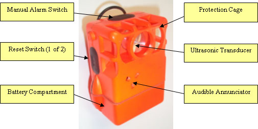
Figure 6-1. The Pulse Beacon Combines an Omnidirectional
Ultrasonic Transmitter with PASS Functions
|
6.1 Beacon
The Beacon, shown in Figure 6-1, is a lightweight device that is carried by the firefighter. The housing of the Beacon is made
from high-temperature, impact-resistant plastic. The unit is battery powered and is turned on automatically by a tethered activation
clip when removed from the storage position by the firefighter. The unit contains several subsystems that provide traditional PASS
functions as required by the NFPA PASS Standards, including a high-intensity audible annunciator, a motion sensor, LED indicator
lights, a pair of reset switches, and a manual alarm switch. In addition to the standard PASS components, the Beacon also houses
an omnidirectional transducer which transmits an ultrasonic homing signal.
When powered up, the Beacon initially tests various sections, turns on the ultrasonic transmitter, generates a series of tones, and
flashes the LEDs to indicate that it has been turned on and is operating properly. The unit then goes into Monitor Mode. While in
Monitor Mode, the microprocessor in the Beacon turns off both the audible annunciator and the ultrasonic transmitter, and checks
the motion sensor. Every time the motion sensor detects motion, the microprocessor restarts a 20-second timer. If no motion is
detected for a period of 20 seconds, the Beacon goes to Pre-Alarm Mode and outputs a warning tone on the audible annunciator. If
motion of the firefighter is detected within the next ten seconds, the unit returns to Monitor Mode and restarts the 20-second timer.
On the other hand, if no motion is detected for the 10 seconds of Pre-Alarm Mode, the unit goes into Alarm Mode, generates a loud
alarm sound with the audible annunciator, and turns on the ultrasonic transmitter. At that point, the Beacon ignores any activity
detected by the motion sensor. The unit will remain in Alarm Mode unless the firefighter pushes both reset switches simultaneously
to return to Monitor Mode. The reset switches are located on opposite sides of the Beacon to reduce the chance of being accidentally
activated by debris. In case of an emergency, the firefighter can also manually force the Beacon into Alarm Mode by pushing the Alarm
button on the top of the Beacon.
The ultrasonic transducer, which generates the Beacons homing signal, is housed in a grille for protection from damage. The grille
is designed to not block the ultrasonic signal. The grille also insures that there is sufficient air space around the transducer so
that the chance that the signal can be blocked by debris is minimized. The ultrasonic signal is transmitted in all directions so that
the Tracker can find the Beacon.
All firefighter Beacons operate at the same ultrasonic frequency, which is crystal-controlled by the Beacon electronics. This
insures system compatibility: every Tracker knows exactly the frequency used by any disabled firefighters Beacon. There are no
incompatibility issues if different fire departments are working together for mutual aid.
A second Beacon, currently in development, operates at a frequency that is different from firefighter Beacons and is used to mark
exits, so that the rescuing team can rapidly reach safety. A third Tot-Finder Beacon, also under development, operates at yet another
frequency and is used by civilians to mark the location of bedrooms, particularly childrens bedrooms.
The LED flashing and the audible annunciator sounds are different for Monitor, Pre-Alarm, and Alarm Modes, so that the firefighter
can readily distinguish the Modes.
The Beacon is powered by a standard 9-volt, alkaline battery, which is housed in a separate chamber to prevent water and other
contaminants from entering the sealed electronics chamber.
6.2 Tracker
The Tracker, shown in Figure 6-2, is a hand-held, ultrasonic receiver that listens for the Beacons homing signal and displays the
strength of that signal so that the rescuer can quickly locate the Beacon. The Trackers ultrasonic receiver is directional, somewhat
like a flashlight. For a direct line of sight, the Tracker is able to detect the Beacon at a distance in excess of 150 feet.
The Tracker has two control switches, one for turning on the power and for selecting the Beacon frequency, and the other switch for
muting the audible annunciator. When first turned on by pressing the Power & Mode Switch, the unit performs a self test and turns on
the LED bar graph indicators, the LED Mode indicators, and the audible annunciator so that the user can verify proper operation. The
Tracker then turns on the red, upper Mode indicator to show that it is listening for a firefighter Beacon. If the user pushes the
Power & Mode Switch again, the unit changes frequency, listens only for Exit Beacons, and the middle, green Mode indicator turns on.
Changing from the firefighter Beacons frequency to the Exit Beacons frequency is similar to changing the channel on a television.
If the user pushes the Power & Mode Switch a third time, the Tracker changes frequency, listens only for the Tot-Finder Beacon, and
the lower, yellow Mode indicator turns on. Pushing the Power & Mode Switch one more time causes the Tracker to return to firefighter
Mode. At any time, if the user pushes the Power & Mode Switch and holds it on for five or more seconds, the Tracker turns off.
|
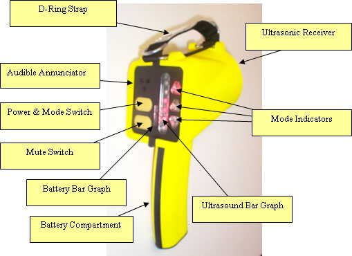
Figure 6-2. The Pulse Tracker is a Hand-Held, Directional, Ultrasonic Receiver
|
When the Tracker detects an ultrasonic signal for the selected Beacon, the strength of the signal is displayed on an LED bar graph.
In addition, the audible annunciator indicates the strength of the signal by changing the beep rate, much like a commercial radar
detector. In order to locate the Beacon, the rescuer scans the area, much like searching with a flashlight, to find the strongest
signal. Then by moving in the direction of the strongest signal, the rescuer will be heading in the direction of the shortest path
to the disabled firefighter. As the rescuer gets closer to the firefighter, the LED bar graph will become higher, and the beep rate
of the audible annunciator will increase. If the rescuer wants to momentarily turn off the audible annunciator so that he can listen
for the Beacons audible annunciator or use a radio, he can push the lower Mute Switch. As long as the Mute Switch is pushed, the
Trackers audible annunciator is disabled; releasing the Switch turns the annunciator back on.
The Tracker housing is fabricated from Ultem, an impact resistant, high temperature plastic. The internal electronics are sealed to
prevent moisture and other contaminants from compromising the electronics. The Tracker is powered by four AA alkaline batteries which
are housed in a separately sealed compartment in the handle. The battery voltage is displayed on a smaller bar graph to the left of
the main ultrasonic bar graph.
6.3 Performance Characteristics
The performance characteristics for the Beacon and Tracker are shown in Table 6-1.
|
Operating Range: |
150+ ft. (direct line-of-sight) |
|
Weight: |
Beacon: |
200 g (7 oz) with battery |
|
|
Tracker: |
408 g (14 oz) with batteries |
|
Batteries: |
Beacon: |
9 v alkaline |
200 hr, approx (Monitor); 2 hr, approx (Alarm) |
|
|
Tracker: |
4 AA alkaline |
25-70 hr, depending on number of LEDs on |
| |
|
Table 6-1. Pulse Performance Characteristics |
In numerous tests and hands-on-training sessions in which search times for blind searches often exceeded 30 minutes, the typical
search time using the Pulse system was in the range of 2-5 minutes for comparable situations.
7.0 Comparison to Existing Systems
7.1 Personal Alert Safety System (PASS)
The Personal Alert Safety System (PASS) is specified by the National Fire Protection Association (NFPA) 1982 Standard, 1998 Edition.
The Pulse system is designed to meet all of the PASS requirements, in addition to adding the ultrasonic homing signal. However, the
system is not yet certified to the NFPA Standard.
Most firefighters are familiar with the difficulty of locating an alarmed PASS device. There are several reasons for this. First,
in order to meet the NFPA specification, the sound intensity of the PASS audible annunciator must be quite high in the range of
100-125 dBa. Unfortunately it is extremely difficult for the human ear to discern small differences in intensity at this high sound
level, which is quite close to the threshold of pain. As a result, the ability to determine the sounds direction is compromised.
In addition, the firefighters helmet and Nomex hood muffle the sound, making it more difficult to determine the direction.
Furthermore, the multiple reflections that typically occur in a fire scene can cause confusion as to the sounds direction. In
addition, the discussion in section 4.2 above sheds some light on the difficulty: alarm signals in the 1 KHz to 4 KHz range (as
specified by the NFPA PASS standard) with an aperture of 7 inches (the approximate distance between a persons ears) result in very
short near fields and poor angular resolution in the far field, having far-field beamwidths in the range of 65 to 259 degrees.
There are numerous examples that illustrate the difficulty of locating a PASS device. One example is trying to determine which of
several possible smoke detectors has the low battery and is chirping. Another example is the response to a cell phone ringing:
everyone in the room checks their own phone, not sure whose is ringing. One of the more tragic examples is the 1999 Worcester fire:
six firefighters perished; their PASS devices were in alarm mode, but they couldnt find each other.
In contrast to the PASS system, the Pulse systems Tracker has a very wide dynamic range coupled with high frequency selectivity.
Because the Tracker knows the exact frequency that the Beacon is transmitting, it is able to filter out all other signal frequencies
and concentrate on only the desired frequency. Furthermore, because the homing signal is at a much higher frequency (approximately 40
KHz), the far-field beamwidth of the Tracker is quite narrow, resulting in a highly directional receiver compared to the human ear.
The Pulse system essentially adds a highly effective locating technology to a PASS device.
7.2 Thermal Imaging Camera (TIC)
The Thermal Imaging Camera (TIC) is a relatively new technology to the fire service. In many ways, the Pulse system is complementary
to thermal imaging. Thermal Imaging Cameras respond primarily to very long wavelength infrared in the 14 micron portion of the
spectrum. One of the biggest advantages of a TIC is that it can see through smoke, because the amount of Rayleigh scattering of
infrared is substantially less than for visible light. As a result, the searcher is able to move more quickly through smoke. However,
because infrared does not reflect well from most surfaces (gold-coated surfaces being the notable exception) a TIC cannot see a
firefighter behind an obstacle or around a corner. Thus the user of a TIC is forced to do a full search of an area. Furthermore, the
TIC has difficulty seeing a firefighter covered by debris. Similarly, the TIC has difficulty in the presence of fog and water spray.
In contrast, because ultrasound is easily reflected from most surfaces, but still passes through porous materials, the Pulse system
can see around obstacles and through debris and fog. Thus the advantages of the two technologies are quite complementary. The
ultrasonic locating technology of the Pulse system could be added to Thermal Imaging Cameras to significantly reduce search times for
both disabled firefighters and exits.
8.0 Summary
Several technology choices are available for the design of a tracking, safety, and navigation system for firefighters, including
optical, radio, and acoustic. Each has its advantages and disadvantages when used in the fire environment. A new system based on
ultrasound has been shown to complement existing products and promises to significantly reduce the search time required to locate
disabled firefighters and exits and thus greatly enhance firefighter safety.
9.0 References
[1]
http://www.wpi.edu/News/Releases/20023/firefighters.html
[2] See Table 39.5 of Electrical Engineering Handbook, Dorf, Richard C, TK145.E354, ISBN 0-8493-0185-8, CRC Press, Boca
Raton, FL, 1993
[3] See Equation 6.21 in Modern Optical Engineering, The Design of Optical Systems, Smith, Warren J, 2nd Edition, TS513.S55,
ISBN 0-07-059174-1, McGraw Hill, New York, 1990
10.0 Biography
Wayne C. Haase
| Email |
whaase@summitsafetyinc.com
|
| President |
Summit Safety, Inc. |
94 Jackson Road, #303 |
Devens, MA 01432 |
| |
|
Phone: (978) 772-9009 |
Fax: (978) 772-7194 |
| Education |
SB |
1965 |
Massachusetts Institute of Technology |
| |
SM |
1967 |
Massachusetts Institute of Technology |
| |
EE |
1969 |
Massachusetts Institute of Technology |
| |
PhD |
1978 |
Stanford University |
| Patents |
13 US Patents |
| Publications |
Approximately 30 technical articles on ultrasonics, aerospace systems, biomedical systems, test and
measurement equipment |
|
|
Updated 05/10/05
© Firefighter image copyright Survivair, 2004. All Rights Reserved.
© Copyright Summit Safety, Inc. 2005. All Rights Reserved.
|
|